A Very Simple Broadband Receive Loop for the Broadcast Band and HF Spectrum - W1AEX
Over
the years, my location has been fairly quiet across
the RF spectrum, but like most places, it has its
moments. In my own house, the paper shredder,
microwave oven, furnace ignition system, eliptical
exercise machine, dvd player, and other assorted
appliances can cause quite a bit of momentary noise
that is picked up by my main transmitting wire antenna
for the 160 - 40 meter bands. In addition, noisy
powerline hardware in the area can cause random noise
now and then. Fortunately, the layout of my yard
allows me to place a few receive antennas about 100
feet away from the house and the most obnoxious noise
generators.
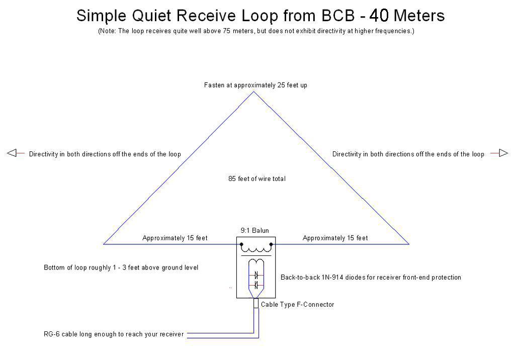
I chose to build the triangular loops because they are cheap, easy, broadband, and exhibit a bi-directional pattern on the lower bands. They also require only one support line at about the 25 to 30 foot level. There is nothing really critical about the construction or symmetry of the antenna, but it is helpful to take the time to orient the loop in such a way that the receive nulls, which are broadside to the loop, are facing the most likely sources of noise. I ended up with a loop that is oriented to favor reception from the north and south on one edge of my property, and another loop oriented to receive from the east and west in another area of the yard. I have found that these receive antennas are quite directional from the bottom of the AM broadcast band through 40 meters. They receive quite well up through the 30 meter band, but at the higher frequencies they behave more as omnidirectional antennas. At 20 meters and above they don't hear much, but I believe that if a preamp were to be placed at the feedpoint they would probably respond well right up through the 10 meter band. The loops are nearly invisible, and fairly indestructible, even through the wind, snow, rain, and sun that we experience up here in the northeast. The total length of wire used in the loop is 85 feet. The schematic of the loop is shown in the figure below:
If you are uncomfortable with the thought of winding
the 9:1 transformer, don't let that put you off. It is
a very simple task to construct it, and there is
nothing really critical about its fabrication. The
core material is mix 43 and the core only needs to be
large enough to let you pass the 30 primary turns and
the 10 secondary turns. Note that I have also wound
transformers using 21 turns/7 turns as well as 15 turns/5 turns and they
seemed to work fine, so experiment if you like. I made a few
transformers with
cores that I recovered from an old crapped out
computer power supply. I have no idea what mix
material they were, but they worked fine. I also
frequently find mix 43 core material at most ham radio
flea markets that sell for about a buck per core. The
pictures below will give you some ideas about how to
make a nice weatherproof transformer.

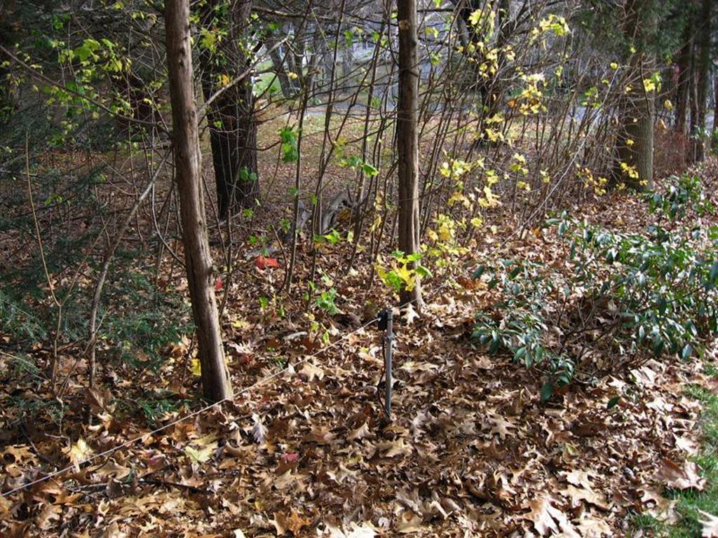
A 4 foot length of conduit is used as a mounting post for the transformer on the north-south loop.
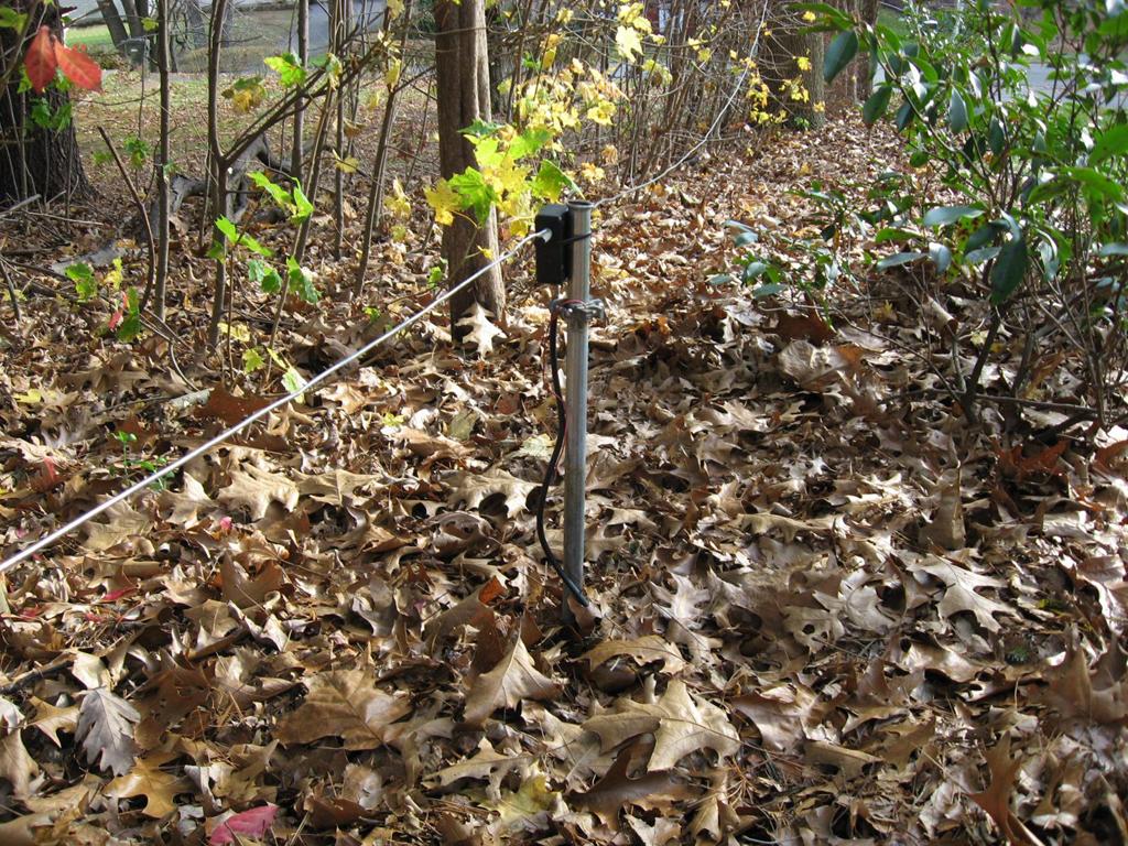

The same mounting arrangement is used for the east-west loop with the preamp mounted underneath.

Tie wraps support the transformer and broadband preamp in the Bud box underneath.
Typically, I find that signals are roughly 20db lower than what is received on the full-size transmitting antenna, however, the signal to noise is vastly improved. To see how the loop performs while listening to a QSO on the 75 meter band take a look at the video below for a short demonstration. The video starts out with the transceiver using the receive loop. Keep an eye on the spectrum scope as it gives a very good indication of when the 256 foot center-fed antenna is switched in by the visible increase in noise across the baseline. At one point, the operating station reduces power and the signal to noise advantage becomes very apparent when the loop is switched in.
The video below demonstrates reception of the AM broadcast band with one of the loops. It does very well across the entire medium wave band as it picks off stations up and down the east coast during a late afternoon listening session. As the receiver is tuned you will see several IBOC signals on the broadcast band. They are characterized by the sound of white noise as you tune through the flat-top digital streams on either side of the analog signal when viewed on the panadapter. The most prominent one in this area is WTIC at 1.080 MHz. The bandwidth of the Flex 5000 is set to 9 KC to prevent hetrodynes from adjacent stations as it is tuned up the band. At 1.480 MHz the bandwidth is briefly widened to 16 KC to enjoy a brief segment of an old song I like. I have found that if I pause for more than 30 seconds on a song that is being played on the air, the YouTube "copyright auto-bot" will flag the video and inform me that the audio will be disabled until the video is reviewed by their staff. Apparently, less than 30 seconds complies with the public "fair use" policy under our legal system's definition of copyright infringement. Note that if you select a viewing resolution of 720p you can view this video in high definition at full screen.
Loop reception on the broadcast band with a Flex 5000A
To install the feedline I slit the soil and run the RG-6 a few inches under the ground to avoid mowing over it with the lawn mower in the summer. The 300 foot length of RG-6 for the north-south loop has been out there for over 20 years and it still works fine! At any rate, these loops are very cheap and easy to make and give me options when the station transmitting antenna is picking up more noise than I wish to tolerate. Once you gather the materials together, it only takes about an hour to get a loop in the air and connected. As a final note, after running the two loops for almost 2 years, I built and installed a W7IUV broadband preamp at the feedpoint of the North-South loop. The performance increase was nothing short of amazing. The video below shows a gain of roughly four S-units on the 40 meter band with the preamp engaged. In the video a weak signal right at the band noise threshold becomes fully readable with the preamp inline. It's fairly obvious when the preamp is "in" and "out" when viewing the video, but the picture below the video shows the difference in recovered audio under both conditions. Needless to say I added a preamp to the East-West loop as soon as the parts came in from Mouser the following week!
Loop reception on 40 meters with a broadband preamp installed

The audio waveform of the video above makes it pretty obvious when the broadband preamp is engaged.
Comparison of the 190' double extended zepp vs. the north-south loop with the preamp active during a 40 meter AM QSO with Rich-K1ETP and Tim-WA1HLR.
For complete construction details visit the page that Larry W7IUV has put together and download his W7IUV Preamp article which is in PDF format. Larry has provided everything you need to know to easily put together one of these outstanding broadband RF preamps. Print out and study his article and any questions you might have will be answered. Normally I would build something like this in dead bug style, but I really liked the way Larry utilized a Dremel tool to make the board so I added a brand new Dremel tool to my collection of things to play with here. As he mentions in his preamp article, it's really easy to create a board for this project and in fact, once I laid it all out it only took about 10 minutes. After looking at a bunch of layouts in Larry's article I ended up with the pattern of isolated pads in the picture below. The picture of my layout is quite a bit larger than the actual board which measures 2.5" x 2.0" so that it fits snugly inside a standard Bud box as in the bottom photo. Note that this design is based upon Larry's 2009 design of the preamp. You should always check Larry's web site for the most up-to-date version of his preamp design as components and the layout may change.
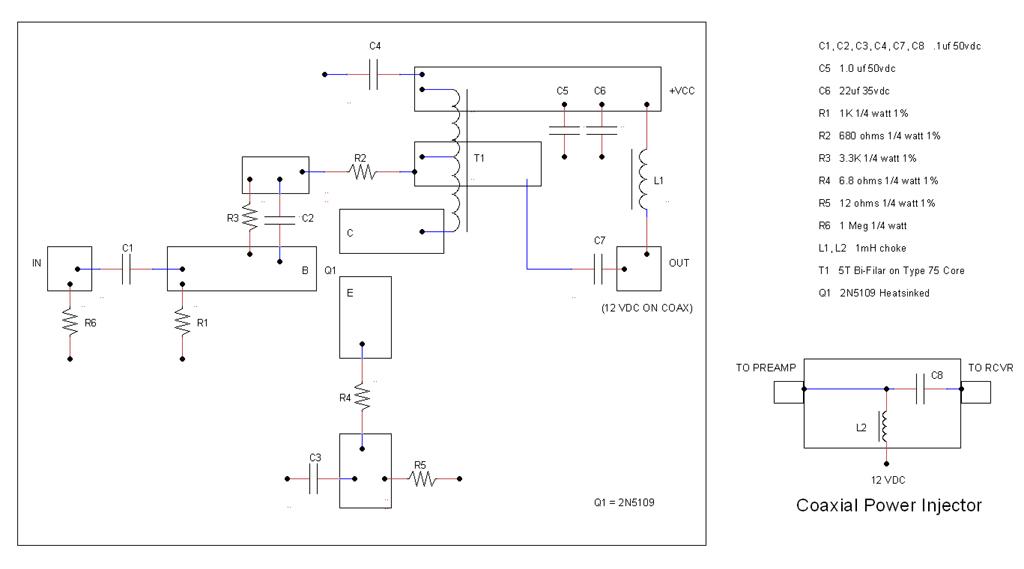
My board layout for the 2N5109
preamp
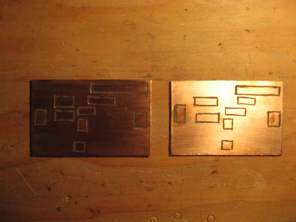
Obviously, I drank too much coffee before making these two boards, but they worked fine.

My first attempt at the W7IUV preamp shown with the cover removed. It works perfectly.
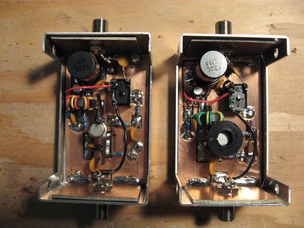
I liked the first one so much that I built two more! The one on the left definitely needs a bigger heatsink before seeing regular use.
I chose to build the triangular loops because they are cheap, easy, broadband, and exhibit a bi-directional pattern on the lower bands. They also require only one support line at about the 25 to 30 foot level. There is nothing really critical about the construction or symmetry of the antenna, but it is helpful to take the time to orient the loop in such a way that the receive nulls, which are broadside to the loop, are facing the most likely sources of noise. I ended up with a loop that is oriented to favor reception from the north and south on one edge of my property, and another loop oriented to receive from the east and west in another area of the yard. I have found that these receive antennas are quite directional from the bottom of the AM broadcast band through 40 meters. They receive quite well up through the 30 meter band, but at the higher frequencies they behave more as omnidirectional antennas. At 20 meters and above they don't hear much, but I believe that if a preamp were to be placed at the feedpoint they would probably respond well right up through the 10 meter band. The loops are nearly invisible, and fairly indestructible, even through the wind, snow, rain, and sun that we experience up here in the northeast. The total length of wire used in the loop is 85 feet. The schematic of the loop is shown in the figure below:


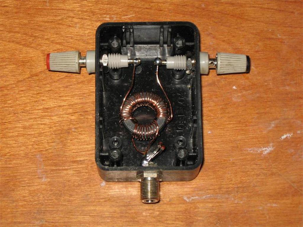
(Note: Solder one lead of
the transformer to the F-connector center conductor and
solder the other lead to the shield connection.)

The
picture
shows a 9:1 transformer built into a Radio Shack
project box.

A 4 foot length of conduit is used as a mounting post for the transformer on the north-south loop.

Tie
wraps hold the transformer in place against the
pipe.

The same mounting arrangement is used for the east-west loop with the preamp mounted underneath.

Tie wraps support the transformer and broadband preamp in the Bud box underneath.
Initially, I simply tied the balun for
the east-west loop to the large tree seen near the
feedpoint in the picture above. Things went well with that
configuration for about a year, and then it got messy as a
squirrel developed an appetite for my RG-6 feedline. He
managed to chomp through the shield in about a dozen
different places that could be reached from the trunk of
the tree, and he actually exposed the center conductor in
one spot. The picture below shows where a few tasty bites
were munched out of the feedline. Fortunately, RG-6 is
relatively cheap, but if it happens again, I may need to
declare war. At any rate, moving it off the tree seems to
have made it a less convenient target, but only time will
tell if the rodents have actually lost interest.


Typically, I find that signals are roughly 20db lower than what is received on the full-size transmitting antenna, however, the signal to noise is vastly improved. To see how the loop performs while listening to a QSO on the 75 meter band take a look at the video below for a short demonstration. The video starts out with the transceiver using the receive loop. Keep an eye on the spectrum scope as it gives a very good indication of when the 256 foot center-fed antenna is switched in by the visible increase in noise across the baseline. At one point, the operating station reduces power and the signal to noise advantage becomes very apparent when the loop is switched in.
Loop reception on 75
meters with an IC-756 Pro III
The video below demonstrates reception of the AM broadcast band with one of the loops. It does very well across the entire medium wave band as it picks off stations up and down the east coast during a late afternoon listening session. As the receiver is tuned you will see several IBOC signals on the broadcast band. They are characterized by the sound of white noise as you tune through the flat-top digital streams on either side of the analog signal when viewed on the panadapter. The most prominent one in this area is WTIC at 1.080 MHz. The bandwidth of the Flex 5000 is set to 9 KC to prevent hetrodynes from adjacent stations as it is tuned up the band. At 1.480 MHz the bandwidth is briefly widened to 16 KC to enjoy a brief segment of an old song I like. I have found that if I pause for more than 30 seconds on a song that is being played on the air, the YouTube "copyright auto-bot" will flag the video and inform me that the audio will be disabled until the video is reviewed by their staff. Apparently, less than 30 seconds complies with the public "fair use" policy under our legal system's definition of copyright infringement. Note that if you select a viewing resolution of 720p you can view this video in high definition at full screen.
Loop reception on the broadcast band with a Flex 5000A
To install the feedline I slit the soil and run the RG-6 a few inches under the ground to avoid mowing over it with the lawn mower in the summer. The 300 foot length of RG-6 for the north-south loop has been out there for over 20 years and it still works fine! At any rate, these loops are very cheap and easy to make and give me options when the station transmitting antenna is picking up more noise than I wish to tolerate. Once you gather the materials together, it only takes about an hour to get a loop in the air and connected. As a final note, after running the two loops for almost 2 years, I built and installed a W7IUV broadband preamp at the feedpoint of the North-South loop. The performance increase was nothing short of amazing. The video below shows a gain of roughly four S-units on the 40 meter band with the preamp engaged. In the video a weak signal right at the band noise threshold becomes fully readable with the preamp inline. It's fairly obvious when the preamp is "in" and "out" when viewing the video, but the picture below the video shows the difference in recovered audio under both conditions. Needless to say I added a preamp to the East-West loop as soon as the parts came in from Mouser the following week!
Loop reception on 40 meters with a broadband preamp installed

The audio waveform of the video above makes it pretty obvious when the broadband preamp is engaged.
Comparison of the 190' double extended zepp vs. the north-south loop with the preamp active during a 40 meter AM QSO with Rich-K1ETP and Tim-WA1HLR.
For complete construction details visit the page that Larry W7IUV has put together and download his W7IUV Preamp article which is in PDF format. Larry has provided everything you need to know to easily put together one of these outstanding broadband RF preamps. Print out and study his article and any questions you might have will be answered. Normally I would build something like this in dead bug style, but I really liked the way Larry utilized a Dremel tool to make the board so I added a brand new Dremel tool to my collection of things to play with here. As he mentions in his preamp article, it's really easy to create a board for this project and in fact, once I laid it all out it only took about 10 minutes. After looking at a bunch of layouts in Larry's article I ended up with the pattern of isolated pads in the picture below. The picture of my layout is quite a bit larger than the actual board which measures 2.5" x 2.0" so that it fits snugly inside a standard Bud box as in the bottom photo. Note that this design is based upon Larry's 2009 design of the preamp. You should always check Larry's web site for the most up-to-date version of his preamp design as components and the layout may change.


Obviously, I drank too much coffee before making these two boards, but they worked fine.

My first attempt at the W7IUV preamp shown with the cover removed. It works perfectly.

I liked the first one so much that I built two more! The one on the left definitely needs a bigger heatsink before seeing regular use.
To power the preamp I feed
the 13.8 VDC through the coax using a little power
injector that I built into an old F connector type switch
box. The voltage travels to the preamp through the center
conductor of the RG-6 feedline and passes to the +VCC
point on the circuit board through a 10 mH choke. The
choke is visible in the upper left hand corner of each
preamp in the photo above. I added a normally closed
bypass relay which can be seen mounted upside down in the
upper right part of the two preamps pictured. When no +VCC
is present the relay connects the antenna input jack to
the preamp output jack through a .1 uf capacitor. This
allows me to use the loop with the preamp turned off. When
power is applied, the relay opens the normally closed
bypass path and the preamp is then functional.
If you are not interested in building a preamp but still want the advantages of all that gain at the feedpoint you might consider looking at the Advanced Receiver Research broadband HF preamps. They are priced very reasonably and I believe they can be powered through the coaxial line using the DC Injector/Bias-T that is sold separately.
If you are not interested in building a preamp but still want the advantages of all that gain at the feedpoint you might consider looking at the Advanced Receiver Research broadband HF preamps. They are priced very reasonably and I believe they can be powered through the coaxial line using the DC Injector/Bias-T that is sold separately.