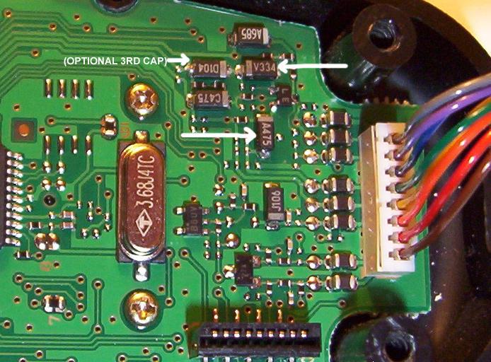
5. Solder a 1.0uf tantalum or electrolytic cap
across the two caps (V334 and A475) on the board, being
careful to work quickly so you do not destroy the tiny solder
pads. Note the position of the positive leads in
reference to the board in the picture below. Bend the
caps down to get them out of the way, and put some
double-sided tape underneath them to keep them from moving or
otherwise stressing the solder joints.
Picture B: Two cap
modification
You can certainly experiment with the values of the caps you
select to pad with. Values between 1.0uf to 10.0uf
should work fine, with higher values favoring more low end
response. I found the additional two caps to produce
pleasant sounding audio, but eventually added a third cap (a
10.0uf tantalum) across component D104 which is just to the
left of component V334 (label is upside down in the
photo above). The D104 surface mount cap is in series with
the audio from the electret and padding that brings up the
low end significantly. Note that a 1.0uf cap will work
just as well here. I liked the result, so my arrangement now
has the third tantalum soldered in place as shown in Picture
C.
Picture C: Three cap
modification
The resulting audio is very full and smooth sounding and
reports have been extremely favorable. The thin
sounding audio of the stock components is just a bad
memory. Keep in mind that the total audio gain is
increased with these arrangements, so you will most likely
need to lower your mic settings in the FT-897 menu. As
an example, I went from a setting of FM MIC GAIN =55 to a
setting of FM MIC GAIN=20.
Parts List:
(2) Radio Shack Part # 272-1434 1.0uf Tantalum
Capacitor 35WVDC max
(1) Radio Shack Part #272-1436 10.0uf Tantalum
Capacitor 16WVDC max
Disclaimer: As always, should you or any of
your IM Force be caught or killed, the secretary will
disavow any knowledge of your actions. This recording will
self-destruct in five seconds. Good luck, Jim. Also,
if you mess your MH59A8J up, I am not responsible.


