Nothing really exotic here.
Mostly it is old stuff that nobody else wanted that has been
restored, or rebuilt, or modified, or homebrewed and then
pressed into service. The station equipment operates on
all bands between 160 meters and 440 mhz with all available
voice and digital modes. Amazingly, the little lunchbox sized
FT-897D which has been retired to 2 meter sideband duty can do
everything the huge mass of iron below can do and more.

W1AEX "Big Rig"

W1AEX "Big Rig"
The first few pictures
show the old AM station in Studio B which is in the
basement. On the left is the Johnson Viking which has been
built into a 6 foot rack to accomodate additional audio
and power supply components. The final of the Viking was
originally a 4D32, but this has been replaced by three
6146B tubes. The original 807 modulator has been scrapped
and replaced by a deck with a pair of 811A tubes and a 300
watt Thordasen transformer. Below the Viking RF deck is
the audio deck, which is composed of two 6550 tubes in a
push-pull Williamson configuration. An audio compressor is
installed just below the audio amp. The Variac above the
Viking RF deck controls the 800 volt plate supply for the
RF tubes and a separate 1250 volt plate supply for the
811A's, allowing power adjustment from milliwatts up to
about 150 watts of RF power. The zero biased 811A's sound
very clean at powers under 1 watt, making this a very
unique QRP rig! I have worked into Great Britain on
10 meter AM using only 1 watt from this rig! As I recall,
one evening back in the 1980's on 160 meters I was able to
work WA1KNX (Dean) about 100 miles to the north with a few
hundred milliwatts. In the fall of 2009 the old Viking rig
was rebuilt into a 3 foot rack and installed in the
upstairs station. On the right side is the 6 foot rack
housing the homebrew 4-400 rig which is bandswitched for
160 - 75 - 40 meters. The 4-400 amplifier deck is
modulated by a pair of 833A's in a push-pull heising
configuration (using a multi-tap plate transformer as the
reactor) suggested to me by Steve - WA1QIX. This rig is
also variac controlled and can run cleanly from around 75
watts input to roughly 900 watts input. The 833A's have a
regulated adjustable bias supply that allows a wide range
of plate voltages to be applied without pushing the
modulators out of class B operation. The antenna for these
rigs is an open wire fed 160 meter inverted vee fed by a
T-Match made from an old GPT-750 CU-658/UR ATU
roller inductor and two huge cardwell bread slicers which
feed into a homebrew 3kw balun. This station warms up
"Studio A" very nicely in the winter!

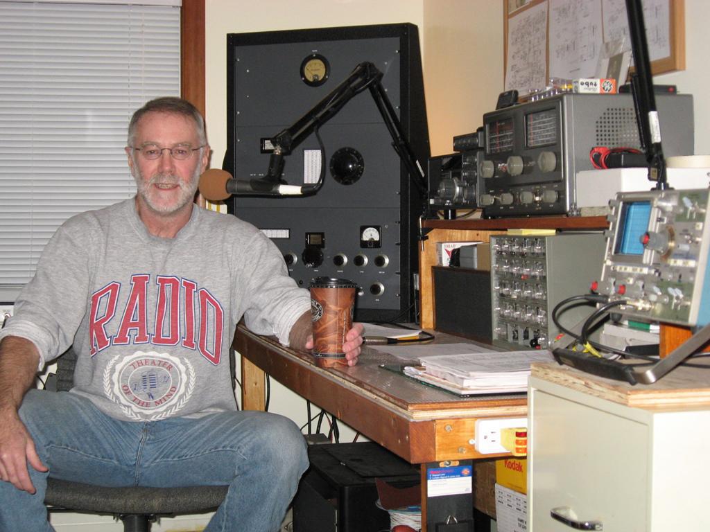
Studio A Operating Position

Studio A Operating Position
The station receiver
is a reliable old SP600 which has been restored and
works very nicely from the bottom of the broadcast
band up through the six meter band. An FM detector has
been built and added to the SP600 just for the fun of
it. The volume control wiper has been tapped and used
to feed audio to a pair of 6L6 tubes which drive a 10
inch KLH acoustic suspension speaker. Not shown
in these pictures is the "Deerfield Special" FRG 7700
shortwave receiver which is used for AM, FM, CW, and
SSB on 160 through 10 meters.
The more modern station shown in the picture below is in the upstairs computer room (actually, to tell the truth, it's more like an arcade). It's an interesting mix of old and new radio equipment. I use the ANAN-200D for all voice modes and a Kenwood TS-590S for the digital modes, BCB listening, and monitoring 6 meters for band openings. Both rigs are assisted by a Mercury IIIS amplifier using a BLF189XRA Ampleon 1700w LDMOS in the PA or an AL-82 amplifier with a pair of 3-500's. The 590S uses a boom-mounted 20 dollar XM8500 dynamic microphone plugged into the front panel. This amazing microphone is a very smooth performer with excellent voice reproduction that rivals much more expensive studio microphones. It's vocal clarity is ideal for amateur sideband use with the typical 3.0K or narrower transmit bandwidths.
The rig that does most of the heavy lifting at this operating position is the Apache Labs ANAN 200D which resides on the lower center shelf between the TS-590S and the AL-82. It's a real workhorse that excels with every mode I run. Even though I have been playing with it extensively it still amuses and amazes me as new capabilities are developed. The primary software that I use is Thetis which offers an assortment of amazing capabilities, including pre-distortion linearization that improves transmitted third order IMD of the entire transmit chain to -50 dB or better. The ANAN is used to drive either the Mercury IIIS or the AL-82 amplifiers and they all work very well together. The ANAN audio chain uses a Marshall MXL-770 studio electret into a DBX 286S voice processor which actually just provides +48vdc for the Marshall electret. The balanced output of the audio chain is fed into a UMC202HD digital interface that is plugged into a USB port on the station computer. The audio is ported into Thetis with VAC and all the audio processing is handled by the broadcast quality CFC Audio Tools inside the Thetis interface. The digital interface approach is very clean and has no discernible latency when the transmitted signal is monitored.

Studio B Operating
Position

The upstairs AM operating position with the resurrected Viking III and FRG-7700

Morning coffee on 40 meters with the Johnson Viking III. What could be better?
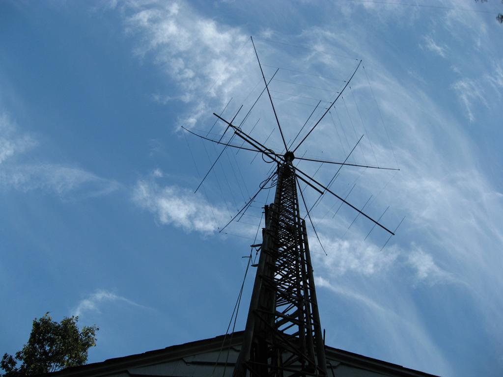
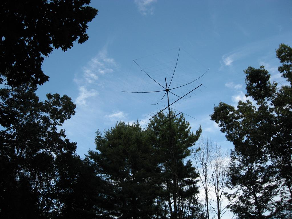
The modest antenna farm is shown below. The tower is a very old EZ-Way 60 foot crank-up and tilt-over galvanized steel monster. It was spotted by my good friend Joe, W1AIU, who tipped me off back in 1987 that it was being retired from commercial service and was available. Purchasing that tower was probably the best hundred bucks I've ever spent in this hobby! It has a 5 foot nosepiece on top and a 14 foot mast above that, which parks the highest antenna at slightly more than 70 feet when the tower is fully extended. Unfortunately, during the infamous snow and ice storm of October 2011 the tower was clobbered by a falling tree. That collision mangled the antennas at the top and put a lot of stress on the tower. During the summer of 2012 it took several weeks to get the tower back into shape along with the 2 meter and 6 meter beams, which were badly bent. A good friend in a nearby town, Bob - K1AO, also suffered severe antenna damage in the big storm. The Traffie Hex Beam that had served him well for 10 years was crushed by several large branches. Bob decided to replace it with a new Hex Beam and offered me his damaged one if I would help him raise the new one. I gladly took him up on his generous offer and with some expert support from Mike Traffie was able to rebuild the old Hex Beam. After some trial runs on a 10 foot pole in the backyard I placed the Traffie Hex Beam at the top of the tower and have been enjoying it ever since. The Hex Beam works beautifully at heights between 30 - 50 feet so out of respect for the age of the old EZ-Way tower I only extend one section of the tower and park the Hex Beam at 50 feet. The rebuilt 2 meter and 6 meter beams are mounted below the hex at heights of 45 feet and 40 feet respectively. With the big Hex Beam upgrade I now have directional coverage from 20 meters through 2 meters. It's been a long time since I've had so much fun on the upper bands!

The rebuilt Traffie Hex Beam cranked to 50 feet

The Hex Beam along with the 2 meter and 6 meter beams up in the clear and pointing south.

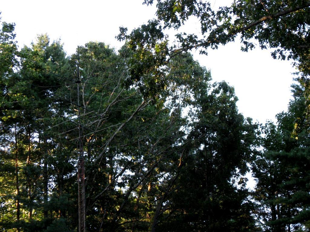
Thanks to a coat of Krylon black paint the tower and antennas blend right into the trees very nicely!
On the VHF side, I use an
M-Squared 3 element beam at 40 feet for 6 meter
AM/SSB with the ANAN-200D. In the picture above,
hanging under the shelf is a TYT 9600 utilizing
the open source GD77 firmware for 2m/70cm DMR and
local FM contacts. The TYT 9600 is used with a
Cushcraft 3 element 2m/70cm beam which uses the
armstrong method for rotation. An FT8900 is also
used for local FM communications primarily on 6
meter FM. It is coupled to a Comet GP-15 at 40
feet on an eave mount mast for 6 meter/2 meter/440
FM work. When running portable, I use a little
Radioddity GD77 running the OpenGD77 firmware for
2 meter and 440 contacts using DMR or FM. For
mobile operating I run a Yaesu FT8900 on 6 meters,
2 meters, and on the 440 mhz band or a TYT 9600
which is also running the OpenGD77 firmware.

The upstairs AM operating position with the resurrected Viking III and FRG-7700

Morning coffee on 40 meters with the Johnson Viking III. What could be better?
The modest antenna farm is shown below. The tower is a very old EZ-Way 60 foot crank-up and tilt-over galvanized steel monster. It was spotted by my good friend Joe, W1AIU, who tipped me off back in 1987 that it was being retired from commercial service and was available. Purchasing that tower was probably the best hundred bucks I've ever spent in this hobby! It has a 5 foot nosepiece on top and a 14 foot mast above that, which parks the highest antenna at slightly more than 70 feet when the tower is fully extended. Unfortunately, during the infamous snow and ice storm of October 2011 the tower was clobbered by a falling tree. That collision mangled the antennas at the top and put a lot of stress on the tower. During the summer of 2012 it took several weeks to get the tower back into shape along with the 2 meter and 6 meter beams, which were badly bent. A good friend in a nearby town, Bob - K1AO, also suffered severe antenna damage in the big storm. The Traffie Hex Beam that had served him well for 10 years was crushed by several large branches. Bob decided to replace it with a new Hex Beam and offered me his damaged one if I would help him raise the new one. I gladly took him up on his generous offer and with some expert support from Mike Traffie was able to rebuild the old Hex Beam. After some trial runs on a 10 foot pole in the backyard I placed the Traffie Hex Beam at the top of the tower and have been enjoying it ever since. The Hex Beam works beautifully at heights between 30 - 50 feet so out of respect for the age of the old EZ-Way tower I only extend one section of the tower and park the Hex Beam at 50 feet. The rebuilt 2 meter and 6 meter beams are mounted below the hex at heights of 45 feet and 40 feet respectively. With the big Hex Beam upgrade I now have directional coverage from 20 meters through 2 meters. It's been a long time since I've had so much fun on the upper bands!

The rebuilt Traffie Hex Beam cranked to 50 feet

The Hex Beam along with the 2 meter and 6 meter beams up in the clear and pointing south.

Thanks to a coat of Krylon black paint the tower and antennas blend right into the trees very nicely!
A GP-15
Tri-Band vertical sits at 30 feet with an eave
mount to offer omni-directional coverage with
a Yaesu FT-8900 for the FM sections of 6
meters, 2 meters, and the 440 MHz band. A
Grove Scanner Beam at 30 feet handles most of
the scanning duties for public
service and aircraft listening. I
can easily hear all the ground control
frequencies at Bradley Field as well as some
of the Military aircraft stuff up north at
Westover and Westfield.

190 Foot Open Wire Center-Fed
For 160/75/60/40 meter operation, I use
90 feet of homemade open wire feedline to
a center-fed 190 foot inverted vee. If you
look closely at the upper center of the
picture, you can see the feedpoint and the
open wire line trailing off at the top of
the picture. The apex is sitting at just
under 70 feet, and the ends are tied off
at 45 feet. The open wire feedline is very
easy to construct and superior in several
ways to the commercially available "window
line" commonly sold by antenna product
vendors. More details about how to
construct your own homemade open wire line
can be seen at
the link here.

190 Foot Open Wire Center-Fed
Before
entering the station the open wire
feedline is connected through an Array
Solutions AS-309H balanced line
lightning arrester that is bolted to a
12 foot steel post pounded into the
ground and staked out with several
eight foot copper clad electrodes. The
AS-309H does a great job of bleeding
off static and when my feed lines are
disconnected as bad weather rolls in
it offers an outside low impedance
straight shot to ground. So far so
good but time will tell...

Array Solutions Open Wire Line
Lightning Arrester