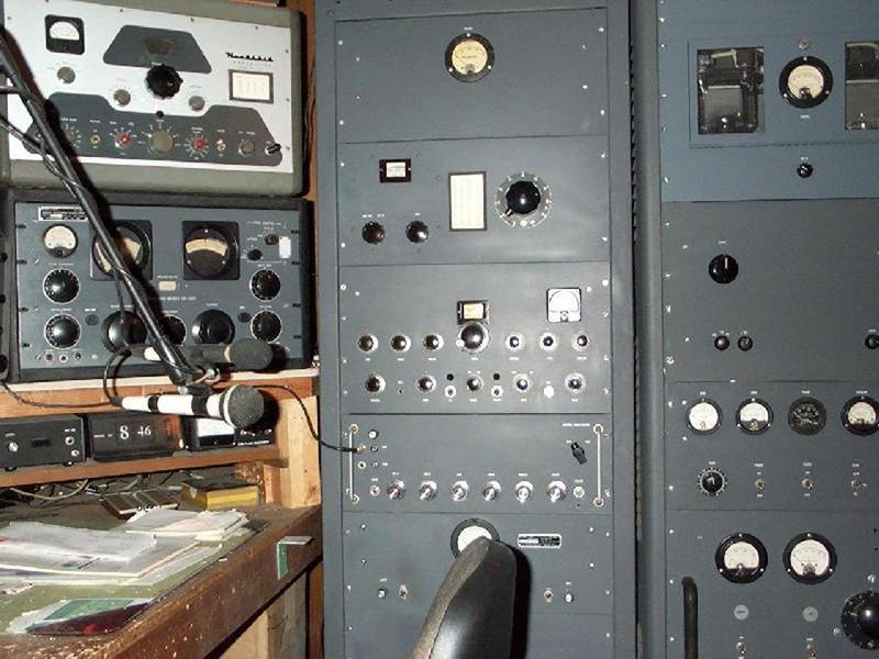
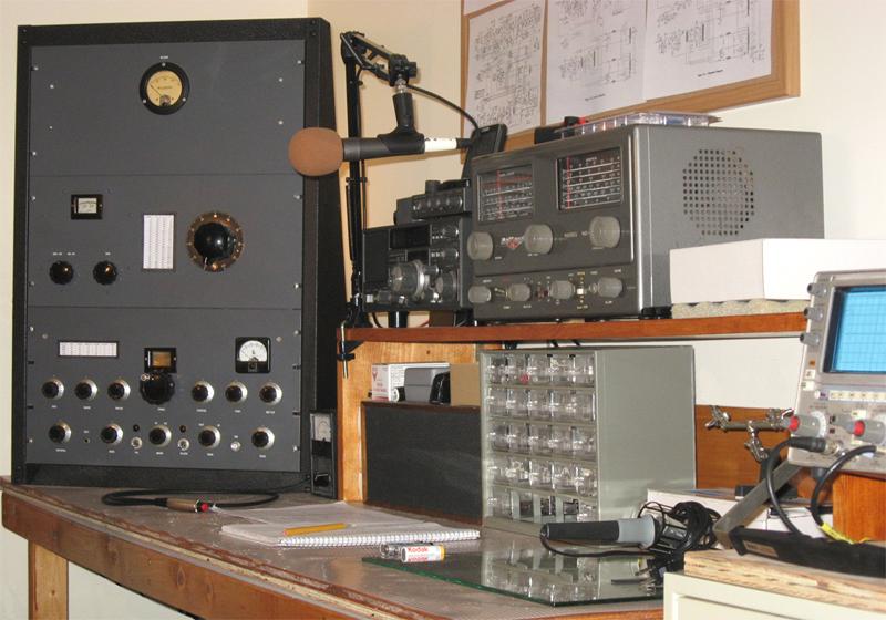
After
sitting
silently in the basement for the past 15 years, the
Viking III has risen once again and now resides happily
in the more comfortable upstairs station. Back in 1975 I
rescued this transmitter, a stock E.F. Johnson Viking I,
from the loft of a barn down in southern Connecticut.
The owner explained to me that he had assembled it back
in the early 50's and stated that he was fairly
terrified of it by the time he got around to powering it
up for the first time. Unfortunately, after hitting the
plate switch, there was a spectacular arc in the tank
circuit as he attempted to tune it up for the first
time, and the fuse blew. He yanked the power cord from
the wall and walked away from it, vowing to never touch
it again. So, there it sat for roughly 20 years, until
he offered it to me for 35 bucks. After cleaning the hay
and mouse turds out of the chassis, I found the cause of
the arcing incident to be a bent plate on the tuning cap
in the tank circuit. After straightening that out, I
fired the rig up and it came to life nicely. As time
went on, and my meager supply of 4D32 tubes would no
longer pull grid current on the upper bands, I installed
3 x 6146's (hence the nickname Viking III) in the final
and mated the RF deck up with an external modulator
using a pair of 811's. I ended up putting the whole
thing, including the VF-122 VFO, into a six foot rack.
It served me well in the basement station for many years
until it eventually was neglected as I finished up my
4-400 rig.


The old
Viking sat dormant for 15 years, which is probably
the worst thing you can do to any piece of
electronic gear. Last winter, I began thinking about
rebuilding the Viking and installing it in the more
civilized upstairs station. So, I broke it down and
grabbed an empty 3 foot rack from my basement
storage and began re-building it. The RF deck needed
a good cleaning, some new electrolytics for the LV
and bias supplies, and a new power cord with a 3
pronged connector. It powered up fine and made a
healthy amount of RF. On the list of things left to
do is to rip out the unused remnants of the harness,
replace the micamold loading caps with doorknobs,
and add a better neutralizing circuit.


The bottom components with lots of unused wiring still in the harness to clean out.

New screen resistor, new electrolytics, unused tube sockets and wiring cleaned out. Good to go!

Rewiring the modulator deck, which has its own 1500 volt plate supply.

Adding in the relays and control circuitry before mounting the Thordarson CHT 300.

Up and running comfortably with 150 watts output.

The RF Deck with 3 x
6146's in the final

The bottom components with lots of unused wiring still in the harness to clean out.

New screen resistor, new electrolytics, unused tube sockets and wiring cleaned out. Good to go!

Rewiring the modulator deck, which has its own 1500 volt plate supply.

Adding in the relays and control circuitry before mounting the Thordarson CHT 300.

Up and running comfortably with 150 watts output.
The rig runs very
cleanly from 1 watt to over 150 watts output. It
actually has been pushed as high as 175 watts out,
but I figure the old micamold loading caps are
stressed plenty at the 150 watt output level. The
variac in the middle panel controls the Viking RF
deck's 750 VDC plate supply as well as the
modulator's 1500 VDC plate supply. At all power
levels, the 811's in the modulator (which sits under
the bench) are running at roughly twice the voltage
of the three 6146's in the RF deck. The low level
audio is generated on one of the station computers,
and equalized with software, which also brickwalls
the audio at about 6 kc. That's a good thing, as the
modulator appears to pass audio out to about 15 kc,
which doesn't make for very neighborly operating on
a crowded band (15 kc + 15 kc = 30 kc). The
output of the soundcard is routed through a JBL 7110
compressor/limiter and then fed into a 40 watt solid
state audio amp that drives the 8 ohm tap of a
backward connected push-pull 6L6 type audio output
transformer, with the transformer primary connected
to the 811 grids. The receiver is an old Yaesu
FRG-7700 which sounds very nice in the 12 kc
bandpass position. A more vintage NC-88 is used for
casual shortwave and broadcast band listening.
On my very first QSO with the resurrected Viking III it was my fortune to be received by Bill, KC2IFR, who was making a few recordings up and down the band. He emailed me a sound clip so I could hear how the rig sounded. There's still a lot left to finish up, but it's been fun playing with the old Viking III on the air once again!
On my very first QSO with the resurrected Viking III it was my fortune to be received by Bill, KC2IFR, who was making a few recordings up and down the band. He emailed me a sound clip so I could hear how the rig sounded. There's still a lot left to finish up, but it's been fun playing with the old Viking III on the air once again!
First
contact running
about 30 watts with
the resurrected Viking III on 75 Meters
During a casual
conversation one afternoon with Tim - WA1HLR he
suggested that I reconfigure the primary to
secondary ratio of the Thordarson CHT-300
modulation transformer. The original 1.73:1
ratio was appropriate for the old 4D32, which
pulled 200 ma of plate current, but the three
6146B's typically pull over 300 ma of current
and present a much lower tank circuit impedance.
Tim determined that a ratio of 2.32:1 would
allow the 811'As to develop much more audio, so
I rewired the primary and secondary taps as he
instructed me to. The end result of that was
much smoother and louder audio with about half
the amount of audio drive power. The clip below
was captured by Eric - WB2CAU on his Flex
SDR-1000.
Thanks Eric for the EQ suggestions! Thank you Tim, for pulling the Thordarson CHT-300 tap connections out of your head! I am always amazed by the vast repository of technical information that he has acquired and retained through his experience over the years. Even more impressive is his willingness to share it with others.
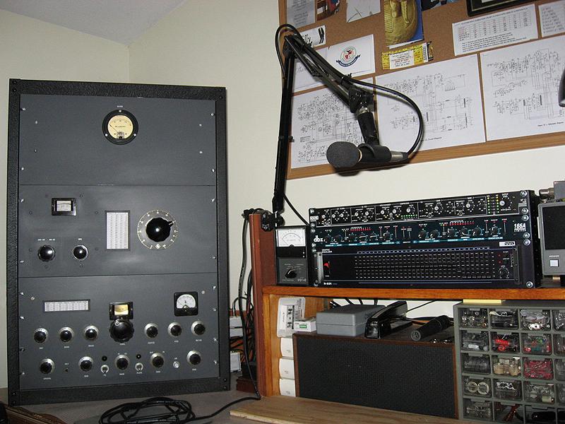
February 2012 update: To make the best use of several transmitters that I like to operate, I decided to assemble a small audio rack that could be easily moved and inserted into various operating positions. The critical piece I needed was a preamp and voice processor that was versatile enough to give me some control over bandwidth, compression, limiting, and equalization. Blane - N1GTU had a beautiful RANE VP-12 Voice Processor that he was willing to sell and after looking over the manual, I realized that it was more than capable of handling all the tasks I had in mind. The RANE, along with my DBX 166A and a DOD 31 band equalizer would provide me with all the tools I would need to restrain the Viking's tendency to get wide and unruly on the bands. The three units would need 7 inches of rack space so I bought a pair of 7 inch rack rails from Parts Express for $6.75 to hold them all together. The rails worked out great and make it very easy to pick up all three units and move them when the audio chain is needed at any of the operating positions.


For best clarity view at 720p HD full-screen
The audio settings in the video are:
First transmission: RANE VP-12 is set for 5kc high-cut and de-esser is set to 4kc with a threshold of -15 dB.
Second transmission: RANE VP-12 is set for 5kc high-cut and de-esser is set to 4kc with a threshold of -15 dB. The DOD 31 band EQ is set to -12 dB cut at 5 kc.
The Viking III transmitter is running 100 watts output into a dummy load while the Flex 5000A receiver is set to the AM mode with a 12 kc bandwidth.
On the air reports have been very good and stations have reported that there are no signs of splatter on either side of the signal. The observed bandwidth by those with panadapter displays indicates effective brick-walled widths of a maximum of 12 kc and 10 kc between the two different setup modes. As it is with all this stuff, the Viking III is an ongoing project that has been lots of fun to mess around with over the past 3 decades.
Back to Main Page
Thanks Eric for the EQ suggestions! Thank you Tim, for pulling the Thordarson CHT-300 tap connections out of your head! I am always amazed by the vast repository of technical information that he has acquired and retained through his experience over the years. Even more impressive is his willingness to share it with others.
February 2012 update: To make the best use of several transmitters that I like to operate, I decided to assemble a small audio rack that could be easily moved and inserted into various operating positions. The critical piece I needed was a preamp and voice processor that was versatile enough to give me some control over bandwidth, compression, limiting, and equalization. Blane - N1GTU had a beautiful RANE VP-12 Voice Processor that he was willing to sell and after looking over the manual, I realized that it was more than capable of handling all the tasks I had in mind. The RANE, along with my DBX 166A and a DOD 31 band equalizer would provide me with all the tools I would need to restrain the Viking's tendency to get wide and unruly on the bands. The three units would need 7 inches of rack space so I bought a pair of 7 inch rack rails from Parts Express for $6.75 to hold them all together. The rails worked out great and make it very easy to pick up all three units and move them when the audio chain is needed at any of the operating positions.

A simple
rack for less than 10 bucks!

The little
audio rack installed at the Viking III
operating position
Being cheap,
I stayed with my usual homebrew
electret condenser microphone and
simply built a voltage divider inside the
microphone case to drop the +48 VDC phantom
power down to less than 10 volts so that the
little Radio Shack electret element would
survive. That worked out fine and to be
honest, the condenser microphone sounds much
more natural than any of the studio dynamics
(Shure SM58, Shure SM57, Shure PE589, Peavey
HD-40 and Peavey CD-30) that I have lying
around. The little audio rack drives a
Lafayette LA-40 solid state amplifier which
drives the 8 ohm tap of a backward connected
HH Scott push-pull audio output transformer
connected to the grids of the 811A
modulators. When I fired up the Viking III
into a dummy load for the first time with
the new audio chain I was stunned by the
amount of control the RANE gives you over
every aspect of the audio. The parametric
equalizer took a little time to figure out,
but when the settings were worked out and
teamed up with the low-cut, high-cut, and
variable de-esser control it was possible to
eliminate the tearing sibilant peaks that
the Viking III tended to produce in the
past. The compressor/limiter made it
possible to bring the average up while
brick-walling the amplitude before 100%
negative peaks were reached. The DOD 31 band
equalizer is used only as a cut-off
bandwidth tool to provide -12 dB of roll-off
above 5000 cycles. The video below of two
different audio setups was made to show what
the Viking III sounds like when run fairly
wide open and when run where bandwidth needs
to be restrained. In both cases, no audio
tearing was evident and no artifacts were
seen outside the transmitted audio
bandwidth, which appeared to be roughly plus
and minus 6 kc in the wider mode and plus
and minus 5 kc with sharper cut-off in the
restrained mode. There are an infinite
number of setups that fall somewhere between
the two examples in the video. You'll no
doubt notice that the audio is very heavily
compressed here as I was deliberately
pushing things very hard to see if it would
misbehave. Normally, I would run this rig
with far less compression to avoid the
rushing audio effects. Note that the rising
baseline in the panadapter on both sides of
the signal in the video is a proximity
effect that is not present when transmitting
on the bands.
For best clarity view at 720p HD full-screen
The audio settings in the video are:
First transmission: RANE VP-12 is set for 5kc high-cut and de-esser is set to 4kc with a threshold of -15 dB.
Second transmission: RANE VP-12 is set for 5kc high-cut and de-esser is set to 4kc with a threshold of -15 dB. The DOD 31 band EQ is set to -12 dB cut at 5 kc.
The Viking III transmitter is running 100 watts output into a dummy load while the Flex 5000A receiver is set to the AM mode with a 12 kc bandwidth.
On the air reports have been very good and stations have reported that there are no signs of splatter on either side of the signal. The observed bandwidth by those with panadapter displays indicates effective brick-walled widths of a maximum of 12 kc and 10 kc between the two different setup modes. As it is with all this stuff, the Viking III is an ongoing project that has been lots of fun to mess around with over the past 3 decades.
Back to Main Page