Setup Guide for Thetis and PowerSDR mRX PS Using the
Broadcast Quality CFC Audio Tools
Update:
Note that the CFC setup procedure is still the same with the
current releases of Thetis, however, the metering is now
much more sophisticated with the new container system. It is
possible now to meter the entire transmit chain adjustment
point levels simultaneously while operating. This is far
more useful than the old single point metering system
displayed below! That being said, the setup process below is
the step-by-step path that should be followed to assure
proper operation. A setup guide in PDF format can be
downloaded at the link below if that is more useful to you:
Initial Settings: To start, go through the levels of
the basic audio chain components to assure that they are set
optimally. The steps below will help you to establish a good
starting point:
1. With the TX multimeter set for MIC, select your source
(Mic in, Line in, or VAC) and then set the audio level so your
voice peaks are regularly reaching close to 0 dB. Note that if you
are using a dynamic microphone you may need to enable the “20 dB
Mic Boost” option located on the "Transmit" tab of the menu.
2. With the TX multimeter set for EQ, open
the Equalizer menu at the top of the GUI console and select the
"10-Band Equalizer" option. Note that you can customize the
frequency point for each EQ slider but it is suggested that you
try the default values initially. Adjust the equalizer sliders so
that your audio source produces a relatively flat response with no
over-emphasis in any part of your voice. Dynamic microphones tend
to have a heavy low-end and electrets can be overly bright so each
type typically needs to be treated differently. When you have
flattened out the response of your audio source so there is no
obvious over-emphasis, set the EQ Preamp slider so your voice
peaks are regularly reaching close to but not exceeding 0 dB.
3. With the TX multimeter set for LEVELER, adjust the
Leveler’s Max Gain setting so your voice peaks are regularly
reaching 0 dB.
4. With the TX multimeter set for ALC, check to make sure
your voice peaks are reaching 0 dB. If necessary, adjust the LEVELER
so that your voice peaks regularly hit 0 dB. Note that this is
essential for the Pure Signal algorithm to operate properly.
5. In the Transmit tab set your Transmit Filter to the desired
bandwidth and then save your settings to a Transmit Profile.
CFC Introduction: The CFC (Continuous Frequency
Compression) components include the PRE-EQ, CFC, POST-EQ,
and the PHASE ROTATOR. Note that all of the CFC settings
are stored within each TX profile they are saved in, to allow
unique settings for each TX profile that you create. The steps
below are suggestions for establishing a starting point to allow
you to use the components to optimize your transmit audio. To
start out, if you have COMP enabled in the Console GUI, disable it
for now. (Note that you may elect to enable that later if you wish
to add a “hard limiting” wideband compression effect to your
transmit profile. Enabling CESSB will significantly raise your
average power output and further accentuate the hard limiting
effect when COMP is enabled.) Also, if Pure Signal is enabled,
temporarily disable it so that the audio you hear with MON enabled
is not pre-distorted.
1. PRE-EQ: In step 2 of the basic audio chain adjustments
above, you set the EQ sliders to produce a relatively flat
response for the microphone or audio rack that you are using and
have set the Preamp slider so that you do not exceed 0 dB on voice
peaks while monitoring the EQ with the TX multimeter. Note that
when the CFC option is enabled, the basic EQ will function as the
Pre-EQ stage. If you are satisfied that your settings produce a
relatively flat audio response, you can move on to the next step.
2. CONTINUOUS FREQUENCY COMPRESSOR: In the DSP menu tab
select the CFC tab and place a check in the “CFC Enable”
and “Post-CFC EQ Enable” boxes. The CFC interface offers an
over-all gain slider called PRE-COMP and 10 individual
sliders that allow you to assign different levels of compression
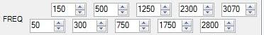
to each assigned frequency point. Note that in the image below you
can see that the frequency points are optimized for a 3K wide SSB
profile. While listening to your transmit audio with MON enabled,
adjust the frequency band sliders upward or downward to control
the amount of “punch” you wish to add to your voice in each area
of the voice spectrum. When you have established settings that
produce the desired level of density for your voice, you can
change the over-all compression level by adjusting the PRE-COMP
slider upward or downward.
3. POST-EQ: While listening to your transmitted signal with
MON enabled, use the Post-EQ form to tailor your transmit
audio’s frequency response. As you can see in the image above, the
Post-EQ sliders are lifting the area from 1750 Hz to the
upper edge of the transmit filter at 3070 Hz to add some
brightness to the transmitted audio. The Post-EQ sliders give you
complete control over the tonal quality of your signal to enhance
clarity, brightness, and low-end response as desired. After
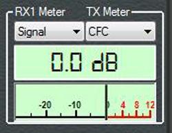
adjusting your sliders, set your TX multimeter to CFC and
than as a starting point, adjust the PRE-COMP slider so
that you are reaching a compression level around 0 dB as you
speak. Note that it's perfectly fine to exceed a level of 0 dB but
you may wish to work with the balance between the PRE-COMP
and POST EQ GAIN settings as described below.
4. Final Adjustments: The new “CFC Comp” meter
shown in the screenshot below displays peak compression levels
that exceed 0dB on a meter scale from 0dB to +25dB. This can be a
very helpful reference to view as you set the compression level of
the CFC components and then adjust the over-all gain of your
transmit profile with the POST EQ GAIN slider. Remember
that the PRE-COMP slider affects the over-all compression
of the CFC components, and the POST EQ GAIN slider adjusts
the overall audio level produced at this point in the transmit
audio chain. If you plan to run fairly a light amount of
compression the CFC meter would probably be the most useful to use
for setting your desired compression level. If you prefer heavier
compression that drives the CFC beyond 0 dB it may be more useful
to monitor the compression level with the CFC Comp
meter.
The two new CFC meters give a nice visual indication of what is
happening as you set the balance between the two CFC gain sliders.
Note that by increasing the PRE-COMP gain slider and
decreasing the POST EQ GAIN slider you will create more
punch and loudness in areas of your audio that you have emphasized
with your CFC slider settings. As the PRE-COMP slider is
advanced you will see the peak compression level of the multiband
compressor increase in the “CFC Comp” meter. For a less aggressive
sounding profile, reduce the PRE-COMP slider until the
“CFC” meter deflects to 0dB or less on voice peaks and then use
the POST EQ GAIN slider to make up the difference in
over-all gain to assure that you are driving the ALC hard enough
to reach 0 dB while monitoring the ALC meter.
For those who wish to enable the console COMP button and CESSB,
excessive output from the CFC components may make your transmitted
audio sound somewhat harsh. To minimize this, try reducing the PRE-COMP
slider so that the “CFC” meter displays maximum peaks of 0
dB or less. Note that when COMP and CESSB are
enabled, the output is hard-limited at 0 dB as shown with the “ALC
Comp” meter. A new adjustment for COMP and CESSB
users is available that allows you to exceed 0 dB of ALC
compression with COMP and CESSB enabled, to make
it possible to use the look-ahead algorithm at the ALC level to
incorporate soft-limiting in the final stage. You can try this new
feature by moving to the DSP menu tab and then the AGC/ALC menu
and using the new ALC “Max Gain” setting. Set the TX
multimeter to view “ALC Comp” and as you speak, you can increase the ALC compression
in 1 dB steps from 0 dB to 10 dB. Several dB of “ALC Comp”
should increase your over-all loudness without added harshness.
5. REMEMBER to save your TX profile: When you are
satisfied with your CFC settings, go back to the Transmit menu tab
and save your profile.
If the directions above seem confusing, the YouTube video below
may make things a bit clearer. Note that this is a 720p HD video
so if you watch it at YouTube it should look sharp and clear when
viewed in theater mode or at full screen.
6. PHASE ROTATOR:
This feature can be used to improve the symmetry of your
voice in your transmitted audio. It’s a very individual
adjustment as everyone’s voice has very different symmetry
characteristics. The steps below will get you started:
• Set the Panadapter in OpenHPSDR to display
the Scope.
• Select a transmit profile that has a fairly
wide response and set the mode to LSB or USB.
• While transmitting, enable the phase
rotator, and as you speak observe your voice pattern on the
Scope display.
• If your voice has more energy above the
horizontal zero axis reduce the number of stages until
better symmetry is observed.
• If your voice has more energy below the
horizontal zero axis increase the number of stages until
better symmetry is observed.
• Try setting the FREQ of the Phase Rotator
to something other than 338 Hz if you believe most of the
energy in your voice is higher or lower.
• When you have found a setting that is
symmetrical with similar energy above and below the
horizontal zero axis, save your TX profile.
If the directions above seem confusing, the
short YouTube video below may make things a bit clearer.